- Accessories
-
LED Products
- Colored LED Lights
- Commercial Out Door LED Fixtures
- Decorative Ceiling
- Decorative Outdoor
- Edge Lit LED Exits Sings
- Generic Ceiling
- LED (Wapor Tight Weahter Proof) WTWP Ceiling Lights
- LED Combo Exit/Emergency Signs
- LED Emergency Lights
- LED Exit Signs
- LED High Bays
- LED Lamps
- LED Low Profile Round Ceiling Lights
- LED Thin Panel Fixtures
- LED Troffers
- Outdoor Area Light
- Recessed
- Recessed Downlight
- Retrofit
- Strip
- Surface Mount
- Undercabinet
- Underthecabenit/Task Fixtures
- Vanity
- Vapor Tight
- Wall Mount
- Retrofit Kits
- Solar Products
- Wire Guards
-
$21.64$37.88
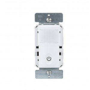
Decorator PIR Occupancy Sensor 150 Degree 4 Wire Ivory
Decorator PIR Occupancy Sensor 150 Degree 4 Wire Ivory
Price Offer: 10/pk Price $158.33/pk
Minimum Order: 2 packs (20 Units) $316.67 (Limited Offer till Stock)
Description: The passive infrared sensors work by detecting the difference between heat emitted from the human body in motion and the background space. The sensor switch can turn a load on and hold it as long as the sensor detects occupancy. After no motion is detected for the set time delay, the load turned off automatically. This product has one relay (equal to Single Pole Switch), also includes adjustable Ambient Light Level.
Features:
Turn lights ON/OFF automatically (Occupancy Mode)
Manual ON / automatically OFF (Vacancy Mode)
Time delay is adjustable from 15 seconds (test mode) to 30 minutes
Neutral wire required
Zero Crossing for long relay life
Adjustable sensitivity settings
Light level is adjustable
Standard decorator wall plate included
Specifications:
Voltage ……………………………………..……………………..…...............................120 Vac, 60 Hz
Incadescent ………………………………………….…………………………...............................500W
Fluorescent …………………………………………..…………….………...............................…500 VA
Motor …………………………………………………………………….…...............................….1/8 HP
Time delay ………………………………………………….…...............................…15 Sec to 30 Mins
Operation temperating …………………………………..………...............................…..32 F to 131 F
*Coverage Area:

Installation & wiring:
1. Connect lead wires as wiring diagram (see Figure 2): Black lead to hot wire, red lead to load wire, white lead to neutral wire, green lead to ground wire.
2. Device “TOP” upward.
3. Gently position wires in wall box, attach sensor switch to the box.
4. Restore power at circuit breaker or fuse, wait one minute.
5. Locate the toggle switch on both sides of the top cover to perform test and adjustment.
Wiring diagram:

Changing the color of your switch
Your switch ships with top cover attached. It is convenient for users to change the top cover. Please proceed as follows:
 |
 |
| Push down top cover to release | Line up tabs and push up to attach |
Testing & Code Compliance
UL LISTE D
California Title 24
Adj ustment:
 |
 |
Band switch prescription:
| Mode | Position | Description | Function of ON/OFF button |
| VAC | Upper side |
Vacancy Mode: Manual On only, Automatic Off after set time delay. |
Manually push On/Off the load. |
| OCC | Lower side | Occupancy Mode: Automatic On, Automatic Off after set time delay. | Manually push On/Off the load. |
Time delay setting:
| Default position | 15 Seconds (Test mode) | ||
| Adjustable | 15 Seconds | 15 Seconds | 15 Seconds |
Ambient light(Default setting):
Notice: If the ambient light level is too high, more than the default setting the load may not automatic turned ON. If turning ON is desired,
cover the sensor lens with one hand for 2 seconds, the light is going to turn ON.
Write a review
Your Name:Your Review: Note: HTML is not translated!
Rating: Bad Good
Enter the code in the box below:


